<test-report/> · HDP30 v1.0 (RevB) · 11 October 2026
HDP30 load-cell test
We bolted a 100 mm arm to the HDP30, drove it into a pair of load cells and turned up the current until something gave. Something did. Here is everything we measured, the plots, and the raw data.
That is well short of the HD20, which we tested to 3.3 N·m. If you need torque today, build the HD20. If you build an HDP30, keep it under about 1 N·m (see what this means for you).
<the-rig/>
A 100 mm arm on the output swings between two load cells, one on each side. Output torque is simply cell force × 0.1 m. The input is a NEMA 17 stepper under closed-loop FOC on an RP2350, with a 21-bit MT6835 encoder on the motor shaft. The output angle comes from an MT6701 reading a ring of magnets on the output, about 12 sensor turns per output turn. Everything is logged at 200 Hz.
The motor runs a speed profile that drives the arm into one cell, stalls there at the current limit, then reverses into the other. The current limit steps up every 12 s, so each push into a cell is a hold at a known motor current.
| Run | What | Motor speed | Current limit |
|---|---|---|---|
| Baseline | Motor alone, arm straight on the shaft, no gearbox | ~10 RPM | 0.1 → 1.2 A |
| Run 1 | HDP30, freshly assembled | 300 RPM | 0.1 → 1.2 A |
| Run 2 | The same HDP30, a few hours later, after run 1 | 150 RPM | 0.2 → 0.4 A |
The baseline gives the motor's own torque constant, 0.151 N·m per amp of measured q-axis current. An ideal 30:1 would therefore make 4.5 N·m per amp at the output. Every efficiency number below is measured against that.
<torque/>
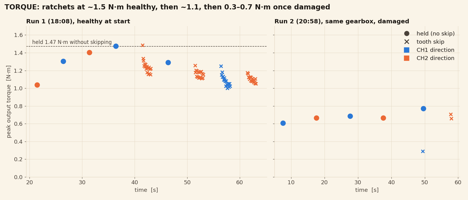
- Healthy, it held 1.47 N·m for two seconds without slipping (0.65 A).
- At 1.48 N·m it started ratcheting, at the next current step (0.93 A). The motor could have pushed harder; the teeth let go first.
- After that it slipped at about 1.1 N·m in both directions, and in run 2 at 0.66-0.71 N·m on impact, and once at 0.29 N·m while simply resting on a stop as the current stepped up.
- The damage is directional. Most of the slipping in run 1 was in one direction, and in run 2 that direction only held 0.12-0.22 N·m.
What ratcheting looks like
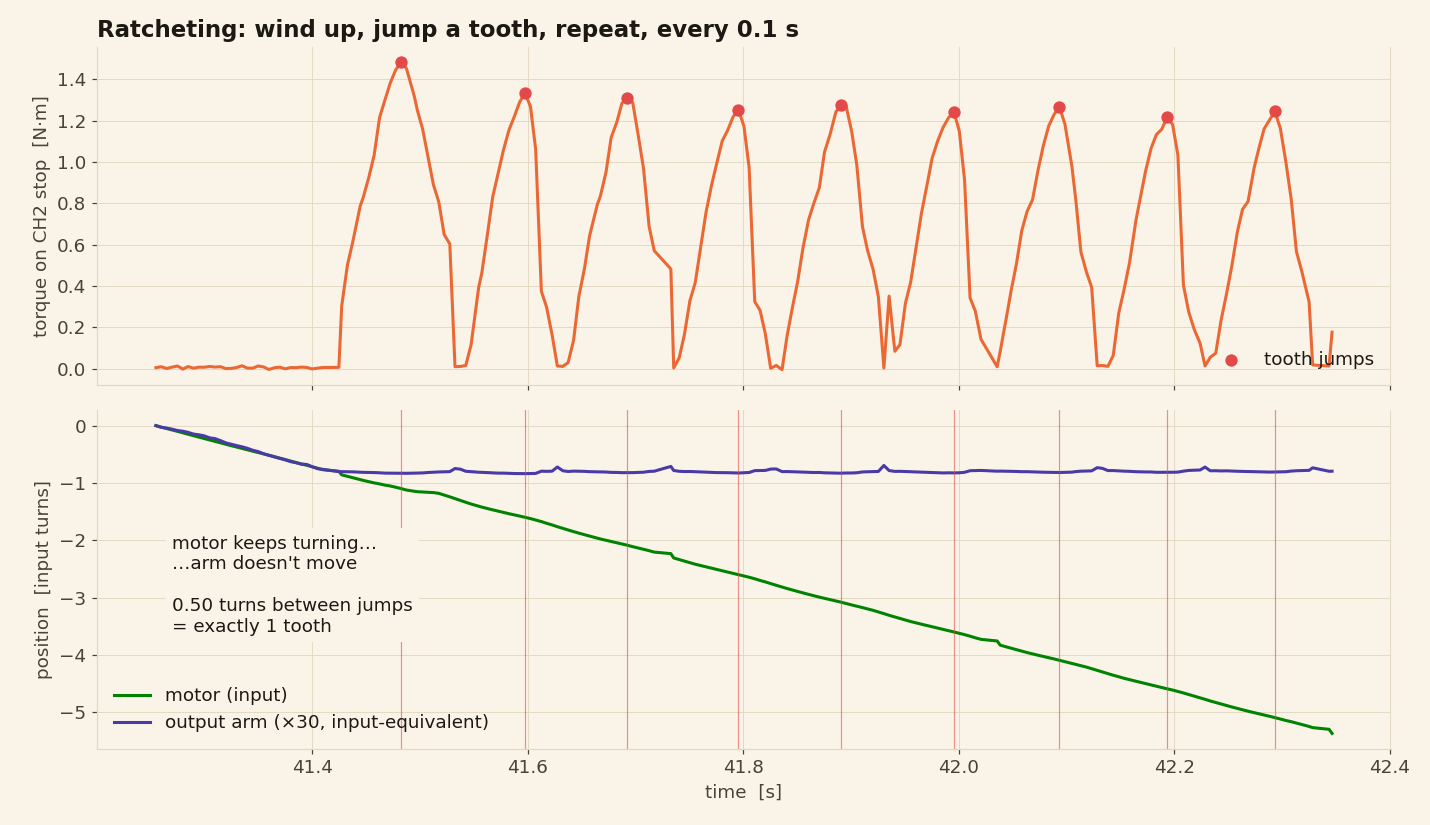
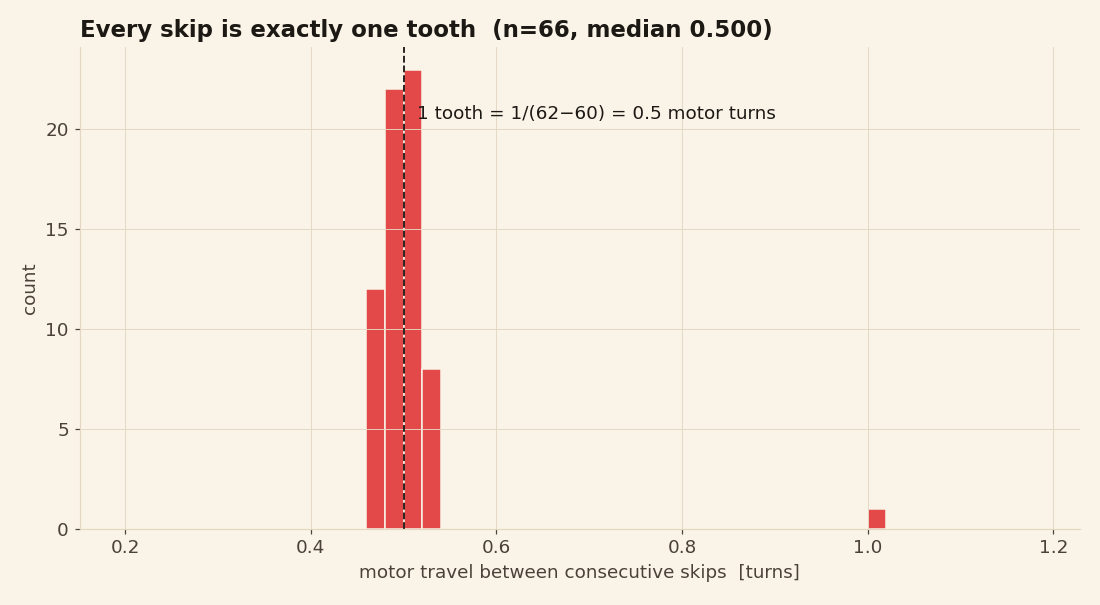
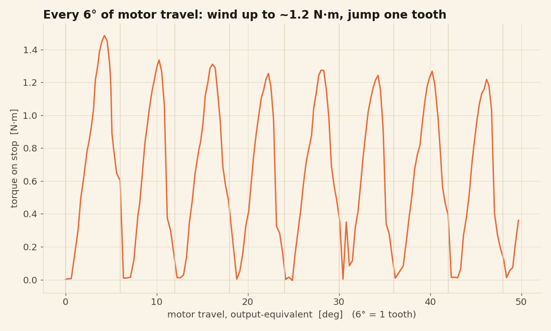
Between jumps the motor turns exactly half a turn (median 0.500, interquartile range 0.49-0.51). With 60 teeth against 62 and the output held still, half a motor turn is precisely one tooth. So this isn't anything breaking all at once: the flexspline is lifting out of mesh and dropping back in one tooth further on.
<efficiency/>
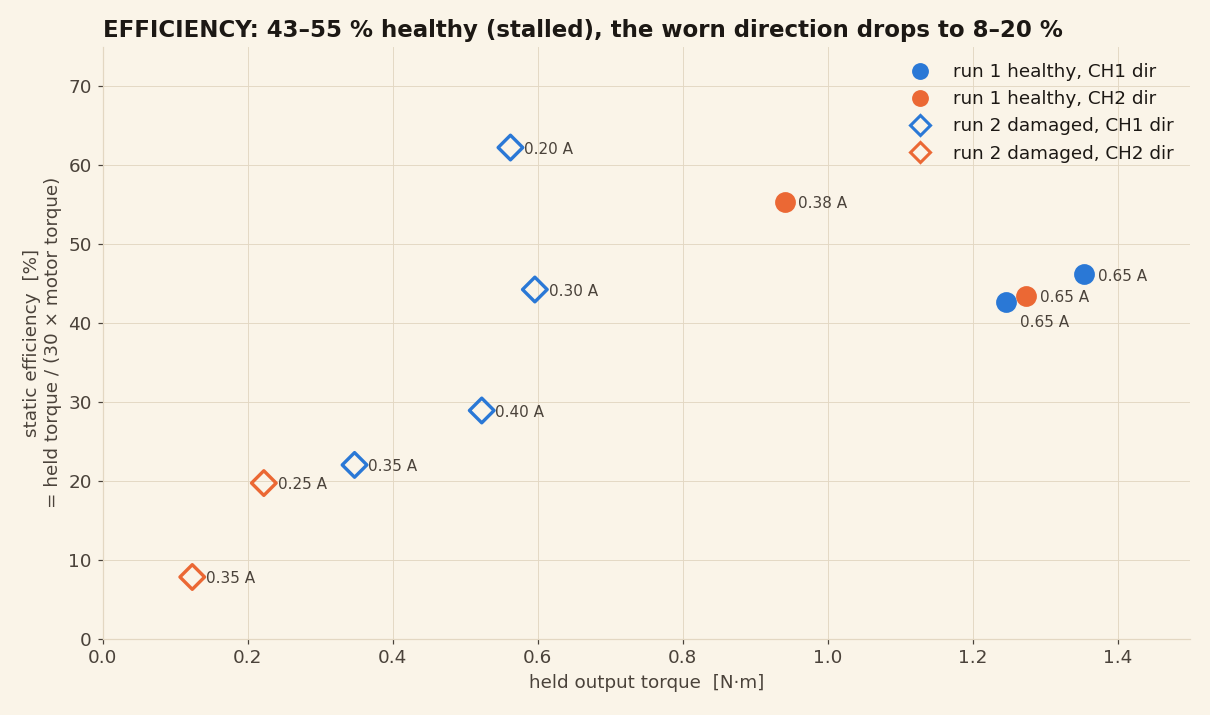
Healthy and stalled, the HDP30 delivers 43-55% of an ideal 30:1, falling as the load rises. That's in the same range as the HD20 (48-58% at 0.7 A, same method). On the damaged unit, the worn direction fell to 8-20%.
These are static numbers: the output only carries load while it's pressed against a cell, so this rig can't measure efficiency while moving under load. With no load, the drive and motor together draw about 0.6 W at 300 RPM, roughly in proportion to speed.
<backlash/>
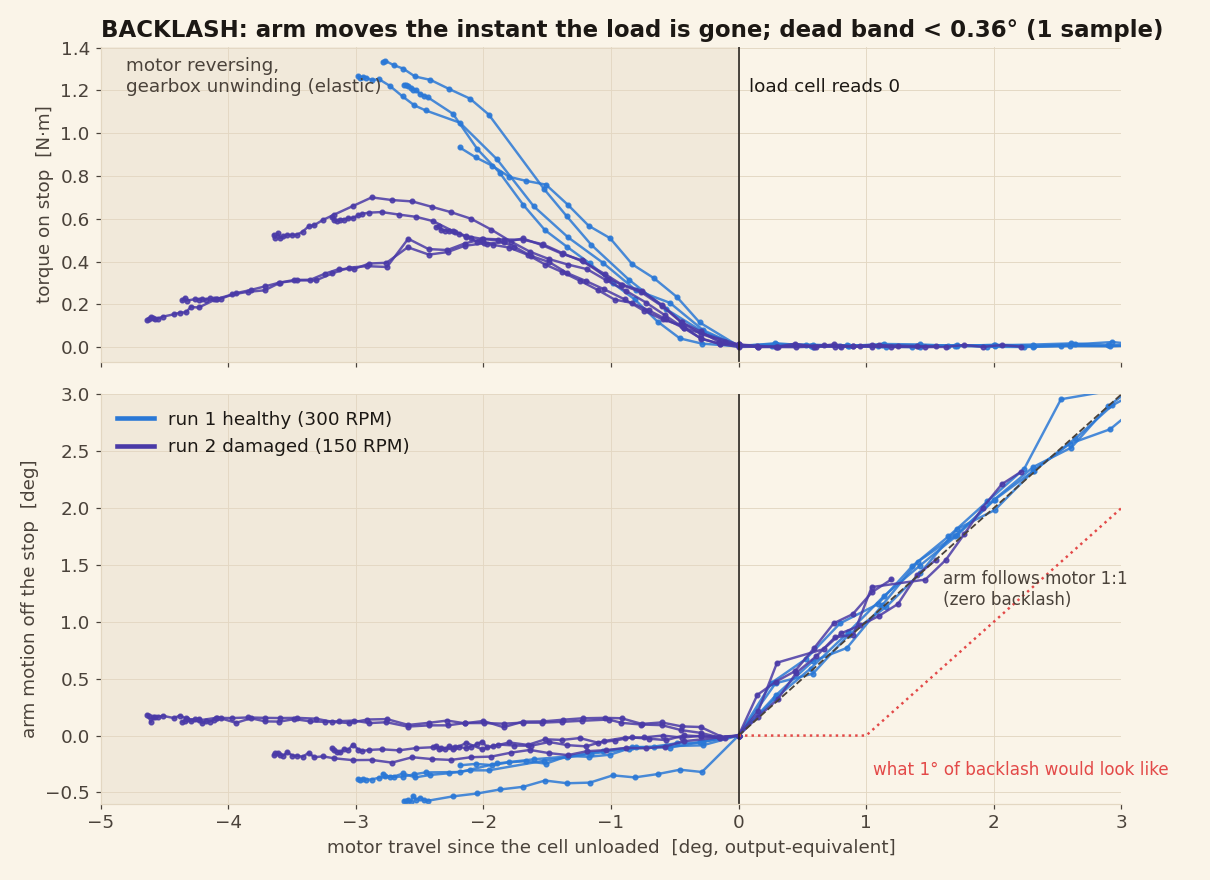
Too small to measure: under about 0.3° at the output. In all ten reversals, the arm started moving within one 5 ms sample of the load cell reading zero. One sample is 0.29° of output travel at 300 RPM and 0.15° at 150 RPM, so any slack is smaller than that.
What you can feel isn't slack, it's give: the drive twists elastically under load (next section). A slow, short-stroke test that never touches the cells would pin backlash down properly, and it's next on the list.
<torsional-stiffness/>
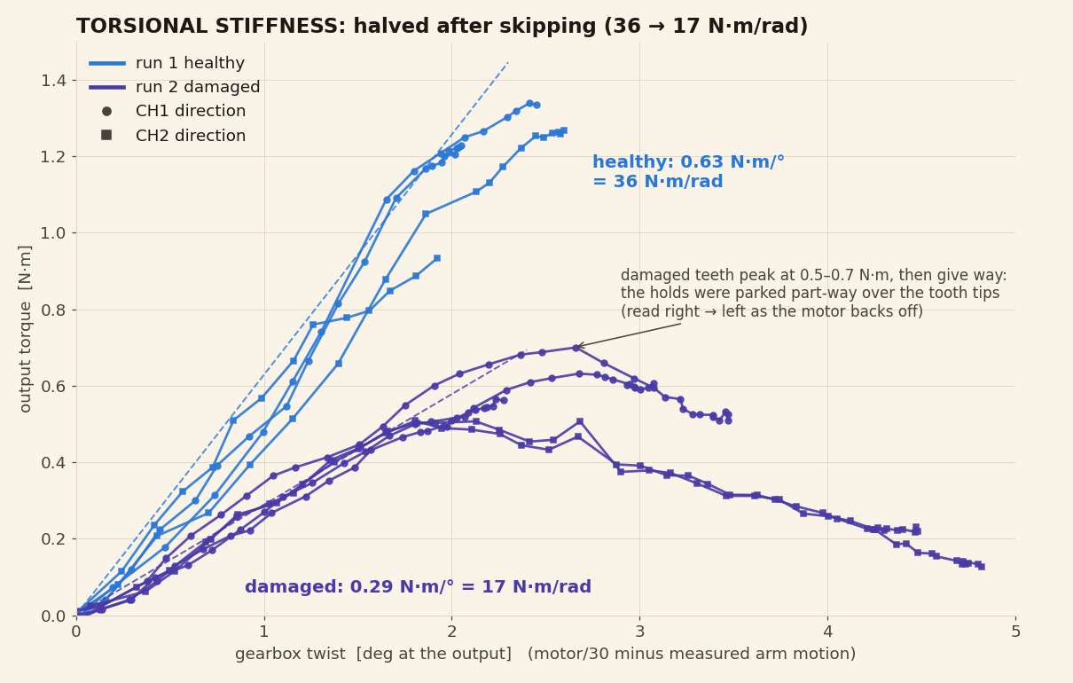
36 N·m/rad (0.63 N·m per degree) healthy, range 31-44 across four holds, and a little stiffer at higher load. At the 1.47 N·m limit that's about 2.3° of twist at the output. After the ratcheting it roughly halved, to 17 N·m/rad.
The damaged curves also show why it got weaker: torque rises to 0.5-0.7 N·m and then falls with more twist. When the arm was held on a stop, the teeth were sitting partway over each other's tips.
Measured on the unloading side of each hold, which starts from rest. The loading side agrees (0.56-0.73 N·m per degree) but includes the impact of hitting the stop at speed.
<hysteresis/>
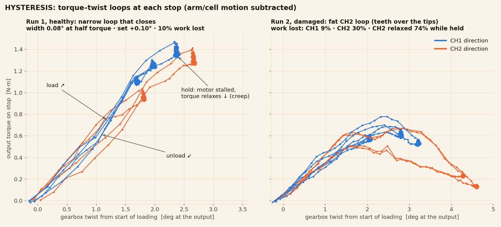
- The loop is narrow and closes. Loading and unloading are 0.08° apart at half torque, and the drive springs back to within 0.1° of where it started.
- About 10% of the work put in is lost per cycle, and most of that is creep, not friction: with the motor held still, torque relaxes about 10% over a two-second hold. That's the PLA and PETG giving slowly under load.
- After damage, the worn direction loses about 30% and relaxes 67-81% during a hold, as the teeth slide down off each other's tips.
<why-it-ratchets/>
Ratcheting means the flexspline teeth are being pushed out of mesh far enough to ride over the circular spline teeth. We don't think there's a single cause, and we haven't isolated one yet. The suspects:
- Tooth separating force. The 30° pressure angle turns a lot of the tooth load into a force pushing the flexspline inward.
- Short teeth. At module 0.55 with 1.08 m addendum, there's only about 0.6 mm of engagement to climb over.
- A thin flexspline wall (0.75 mm PETG) that can deflect inward.
- Give in the wave generator: the printed ellipse and the loose-ball cage behind it.
- Wear after the first skip, which rounds the tooth tips and explains why each round of ratcheting starts lower.
RevC changed the flexspline material and its alignment, and stopped the skipping up to 1.49 N·m. Got a theory? Open an issue.
<what-this-means-for-you/>
- Keep it under about 1 N·m. Set your motor current limit so the drive can't reach the ratcheting point. On our rig, 0.375 A held 0.94 N·m and 0.65 A held about 1.3 N·m, but your motor and driver will differ.
- One overload costs you capacity for good. A burst of ratcheting lowered this unit's limit from 1.5 to as little as 0.3 N·m. If yours has ratcheted, assume it's weaker now.
- Avoid slamming hard stops at speed. Impacts gave the highest peaks we saw.
- If you have an output encoder, watch for a skip. Compare motor angle ÷ 30 against the output, and stop if they drift apart by more than about half a tooth (3° of output). That would have caught this unit at its very first skip.
<method-and-caveats/>
- One unit. Printed parts vary; two HD20s differed by up to 18%.
- Peaks include impact. The arm hit the cells at speed, so the first moment of each push overshoots the static torque. Holds are medians over the steady part.
- Resolution. 200 Hz logging limits backlash and hysteresis to about one sample of motor travel. A few milliseconds of lag in the load-cell reading would make the hysteresis loop look narrower than it is, so read 0.08° as a lower bound.
- Output encoder scale. The magnet ring gives 11.96 sensor turns per output turn in free travel, a few percent off locally. Stiffness and hysteresis only use small motions at a fixed spot, where that error cancels.
- Efficiency is static. See above.
<raw-data/>
Every number on this page comes out of these files. Columns are
time_s, ch1_n and ch2_n (load
cells in N), input_deg (motor angle, wrapped 0-360°),
output_deg (MT6701 angle, wrapped, about 12 turns per
output turn), current_cmd_a (current limit) and
iq_a / id_a (measured FOC currents). Put the
CSVs in a folder with the scripts in a subfolder below it, and run
python analysis.py then python key_metrics.py.
Looking for the older drive's numbers? The HD20 torque test is in the archive.