<archived/> · v1.0 (RevA)
HD20
A 3D-printable 20:1 harmonic drive that bolts onto any standard NEMA 17 stepper. Prints on a normal printer, assembles with about $4 of hardware, and has been tested to 3.3 N·m.
Free and open under CC BY-SA 4.0. Build it, change it, sell it. Just credit us and share alike.
<how-it-works/>
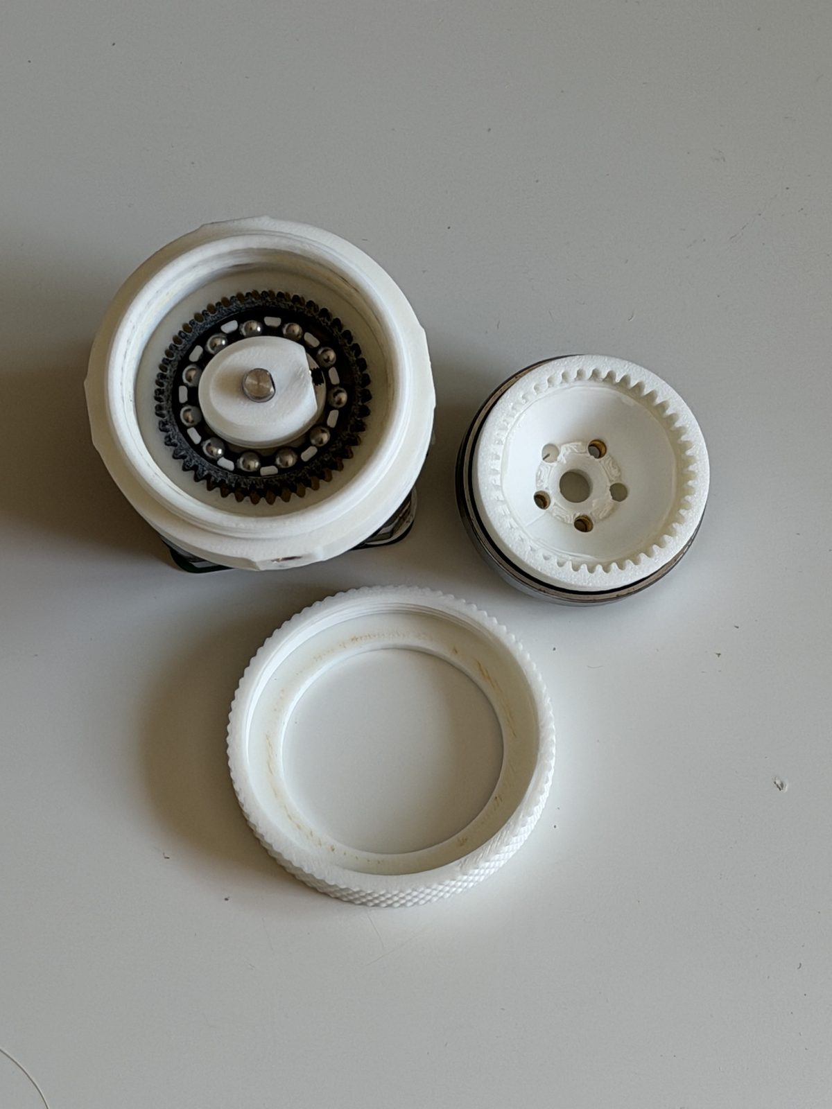
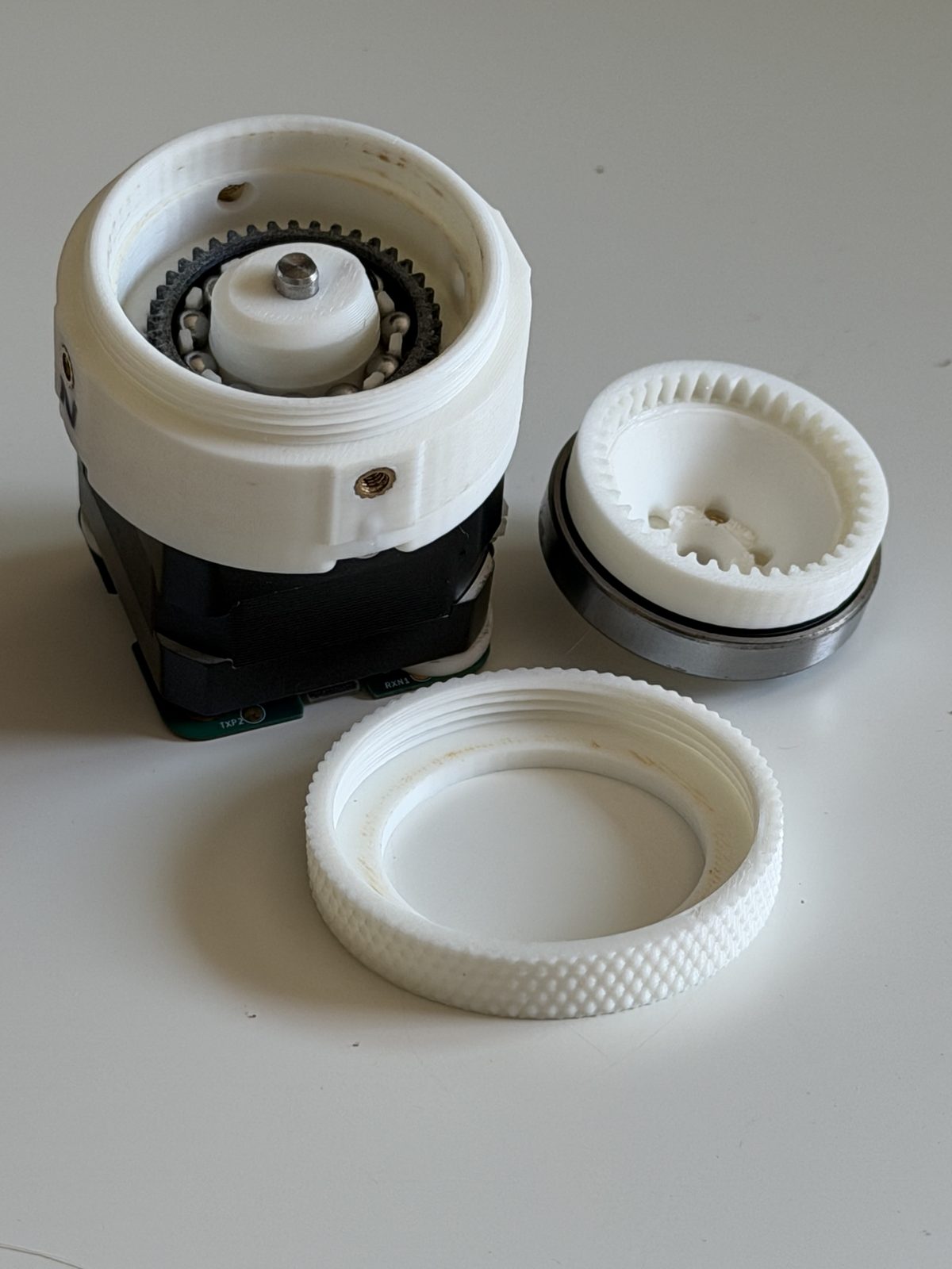
Three parts do the work. A wave generator, an ellipse riding on eleven loose 5 mm balls in a printed cage, pushes a flexible toothed ring (the flexspline) into an oval, so its teeth engage a rigid circular spline at only two points. The circular spline has two more teeth than the flexspline, so a full turn of the motor walks the output around by just two teeth. That tiny slip per revolution is the 20:1.
New to strain wave gearing? We wrote a plain-language explainer. And the tooth profile in this drive came out of our own free harmonic maker. You can use it to generate profiles for your own designs.
<specs/>
| Reduction | 20:1 |
|---|---|
| Tooth profile | Cycloidal, module 0.8 |
| Measured torque | 2.1-2.6 N·m @ 0.7 A · 3.0-3.3 N·m @ 1.4 A (peak 3.5 N·m) |
| Efficiency | 48-58% |
| Backlash | measurement in progress; we'd rather publish nothing than a guess |
| Motor | Any NEMA 17 with a 5 mm shaft. Tested with an OMC StepperOnline 17HE12-1204S: 42 × 42 × 30 mm, 26 N·cm, 1.2 A, 4-wire. |
| Lubrication | Super Lube synthetic PTFE grease |
| Printed parts | 10 pieces across 9 unique parts, including 2 shear pins |
| Fasteners | 8 × M3×0.5 × 6 mm button head screws per drive |
| Materials | PLA throughout, PETG for the flexspline |
| Version | v1.0 (RevA), 9 August 2026 |
| License | CC BY-SA 4.0 |
<what-you-need/>
Beyond the bill of materials below, you supply:
- A NEMA 17 stepper with a 5 mm shaft. We used an OMC StepperOnline 17HE12-1204S (26 N·cm, 1.2 A) under closed-loop FOC control. An open-loop stepper on a basic driver will behave differently.
- 4 × M3 screws to bolt the motor to the interface plate. These are separate from the 8 × M3×0.5 × 6 mm screws that hold the drive itself together, which are in the bill of materials.
- A soldering iron for the heat-set inserts, and hex keys.
- PLA for everything, and PETG for the flexspline.
- Super Lube on the wave generator and the tooth mesh. It's in the bill of materials below. Don't run it dry.
<bill-of-materials/>
loading the bill of materials…
<printed-parts/>
| Part | Qty | Material |
|---|---|---|
| Circular spline (base) | 1 | PLA |
| Circular spline (output) | 1 | PLA |
| Base preloader | 1 | PLA |
| Output preloader | 1 | PLA |
| Interface / motor mount | 1 | PLA |
| Wave generator | 1 | PLA |
| Ball cage | 1 | PLA |
| Flexspline | 1 | PETG |
| Shear pin | 2 | PLA |
Both shear pins are required. They carry shear load across the output joint directly, so the connection doesn't have to rely on friction from the preloaded screws to resist it. The screws clamp; the pins take the sideways load.
Print settings
No custom temperatures and no special bed prep. The tested units were printed on a Bambu Lab P1S with Bambu PLA (and PETG for the flexspline), using the Arachne variable-width wall generator and one extra wall loop for strength.
Two things are not the default. The output circular spline and the interface both need supports; everything else prints unsupported. And we set seam position to random on all parts, so a single seam line doesn't stack up into a weak spot or a visible ridge on the round surfaces.
<the-files/>
Everything lives in robrotics/hd17, which stays online and stays downloadable. Grab the packaged bundles from the releases page. The STEP files are large, so you probably don't want to clone the whole repo. The newer HDP30 lives separately at robrotics/hdp30.
There are no pre-sliced files. Import the STEP into your slicer and use the print settings above, so the geometry you print is always the current one.
<assembly/>
📹 no video for this revision
We never filmed the HD20 build. The HDP30 assembly walkthrough covers the same sequence: the stack-up, the preload and the shear pins are identical between the two, so follow that one and substitute these parts.
<known-behaviour/>
Read this before you conclude you assembled it wrong.
- Torque drops about 10% after running in. A freshly printed unit measured 2.32 N·m; the same unit after further running measured 2.08 N·m at 0.7 A. Plan around the run-in figure, not the fresh one.
- Output spline preload is your biggest tuning knob. Further tightening it took one unit from 2.37 to 2.55 N·m.
- Unit-to-unit variation is real. Two units of the same design differed by up to 18% at the same current. Printed gearboxes are not precision parts.
- Roughly half your motor torque becomes heat at 48-58% efficiency. Size the motor accordingly.
- PLA creeps under sustained load. Holding a heavy static load for hours will slowly deform the circular splines.
- The 1.4 A figures are above the test motor's rating. The 17HE12-1204S is rated 1.2 A, so our 3.0-3.3 N·m numbers were measured over-driven. Treat them as a short-burst ceiling, not a continuous rating. At 1.4 A that motor will get hot.
Hit something we haven't listed? Please open an issue and tell us your version, filament and printer.
<test-data/>
We measured this on a load cell with a 100 mm lever arm rather than guessing from motor specs: seven configurations, 1,500-3,000 samples each, with a no-gearbox baseline to compute efficiency honestly.
read the full torque report →<make-your-own/>
The full parametric model is public on Onshape. Copy it into your own workspace and change whatever you like: a different motor face, a different output interface, a different ratio. If you build a variant we would genuinely like to see it: open an issue on the repo or tag @robrotics.
open the model in onshape →