<test-report/> · Rinnegan drive (HDP30) v2.0 (RevC) · 18 October 2026
Rinnegan drive load-cell test
v1.0 ratcheted at 1.48 N·m. For v2.0 we printed the flexspline in PLA, lined it up properly and put it back on the same rig. It stopped skipping teeth. Then we ran a second one until it broke, and a third one slowly enough to measure its backlash: about 2 arcmin.
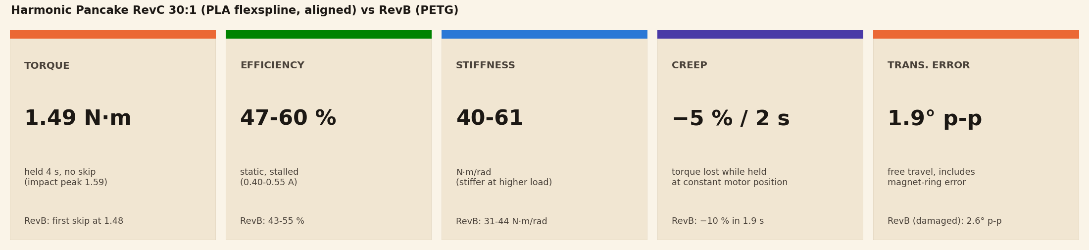
The skipping is gone too: v2.0 held 1.49 N·m for four seconds without losing a tooth, past the point where v1.0 started ratcheting. It's stiffer, it creeps half as much, and the efficiency is the same or a little better.
But the limit moved to the flexspline itself. After this recording we pushed further and heard the PLA flexspline wall crack from about 1.5 N·m, and it broke at about 2.0 N·m. So 1.5 N·m is the ceiling, not a working load.
So we built a second unit and ran it until it broke. It took 5,744 flex cycles and 188 hard stops at 1.0-1.2 N·m with no damage, then cracked after a single 1.67 N·m impact. The working limit is peaks under about 1.3 N·m (see what this means for you).
<what-changed/>
- Flexspline material: PETG to PLA. Same geometry, same tooth profile.
- Alignment. A printed alignment tool sets the wave generator at the right height on the motor shaft, so the flexspline sits square in both circular splines. Both circular splines also gained a third shear pin.
Two changes at once means we can't fully split the credit. Where the data points one way or the other, we say so below.
<the-rig/>
Same rig as the v1.0 test: a 100 mm arm on the output swings between two load cells, so output torque is cell force × 0.1 m. The input is a NEMA 17 under closed-loop FOC on an RP2350, with an MT6835 encoder on the motor shaft and an MT6701 reading a magnet ring on the output. The motor ran at 150 RPM, with current limits of 0.40, 0.40, 0.55 and 0.70 A.
Every efficiency number is measured against the bare motor's torque constant from the v1.0 baseline run, 0.151 N·m per amp, so an ideal 30:1 makes 4.5 N·m per amp.
<torque/>
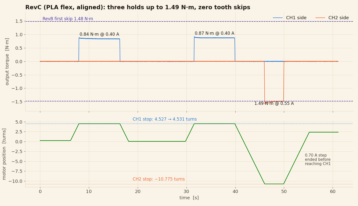
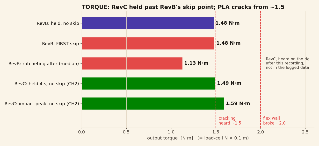
- It held 1.49 N·m for four seconds at 0.55 A, with a 1.59 N·m peak as the arm hit the cell. v1.0's first skip was at 1.48.
- Zero tooth skips. One skip moves the stop by exactly half a motor turn. The stops repeated to within 0.004 of a turn.
- Then the flexspline cracked. Not in this recording: when we pushed further, we heard cracking from about 1.5 N·m, and the PLA flexspline wall broke at about 2.0 N·m. We didn't hear or see it ratchet first.
<torsional-stiffness/>
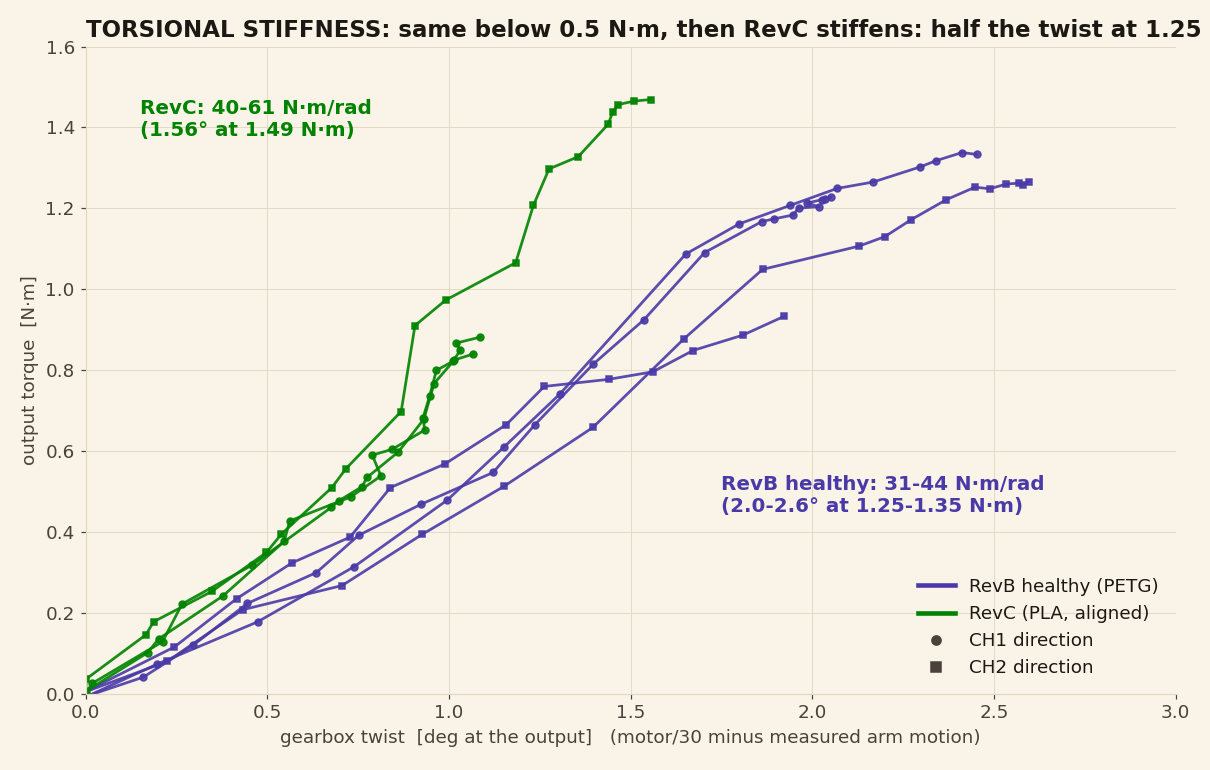
40 N·m/rad at 0.85 N·m, rising to 61 N·m/rad at 1.5 N·m. v1.0 was 31-44 N·m/rad. At 1.25 N·m, v2.0 twists about 1.2° at the output where v1.0 twisted 2.0-2.6°.
The shape matters more than the number. Below about 0.5 N·m the two revisions are the same. Above that, v2.0 gets stiffer as the load rises, which is what you'd expect if more teeth share the load as it grows. That points at the alignment. A stiffer material on its own would have raised the whole curve, including the low-load part, and it didn't.
<creep/>
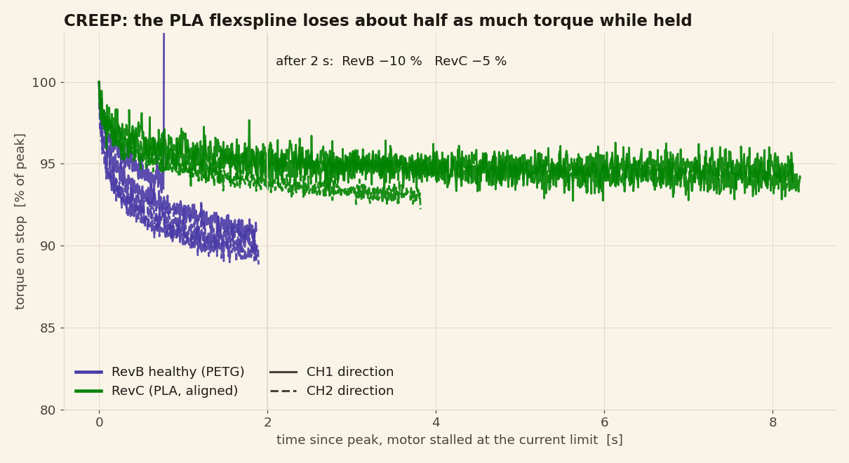
About 5% in two seconds, then it levels off. v1.0 lost about 10% in the same time. This one is the PLA: it creeps less than PETG at room temperature.
<efficiency/>
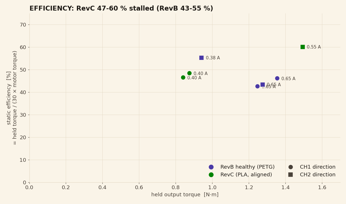
47-48% at 0.40 A and 60% at 0.55 A, against 43-55% for v1.0. All the lower readings were in one direction and the 60% was in the other, at a higher current, so we can't yet say whether that's the load or the direction. No-load drag at 150 RPM is the same as v1.0, so the alignment didn't add friction.
<hysteresis/>
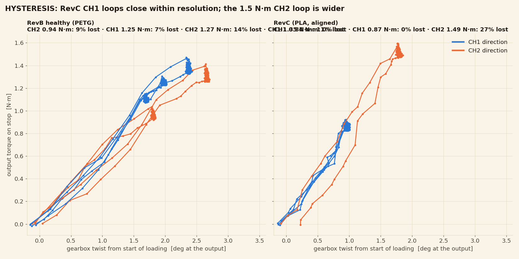
- At 0.85 N·m the loops close, inside what the rig can resolve.
- At 1.49 N·m the loop is wider: 27% of the work put in was lost, and the drive came back 0.26° short of where it started. Creep only explains a fraction of that. Knowing that cracking starts right around this torque, it fits the wall beginning to give. It's a single hold, so treat it as a hint, not a measurement.
<backlash/>
About 0.03° at the output (2 arcmin), and no run showed more than about 0.1°. The fast runs above couldn't resolve it: at 150 RPM one sample is 0.15° of output travel, and a few milliseconds of timing between the two encoders swamps any slack. So on 23 October we built a third unit (fresh PLA flexspline) and ran it slowly: 12 runs at 5 input RPM, three each way at 0.4 and 0.6 A. Each run starts from rest, pushes into one cell, stalls, then backs off. At 1° per second at the output, one sample is 0.005°.
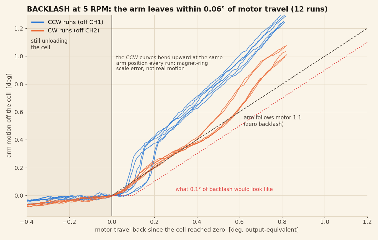
We measured it three ways, all in output degrees:
- Free-travel gap: 0.024° median (8 runs with enough free travel). It compares the motor position at the same arm reading on the way in and on the way back. Comparing at the same reading cancels the uneven spacing of the output encoder's magnets, so this is the cleanest of the three.
- Departure: about 0.03°. After the cell reads zero, the arm moved 0.03° within a median of 0.059° of motor travel, and about half of that is the threshold itself.
- Start lag: about 0.04°. From rest after a reversal, the arm moved within a median of 0.070° of motor travel. The one run that started without a reversal read 0.028°, which is the threshold and noise alone.
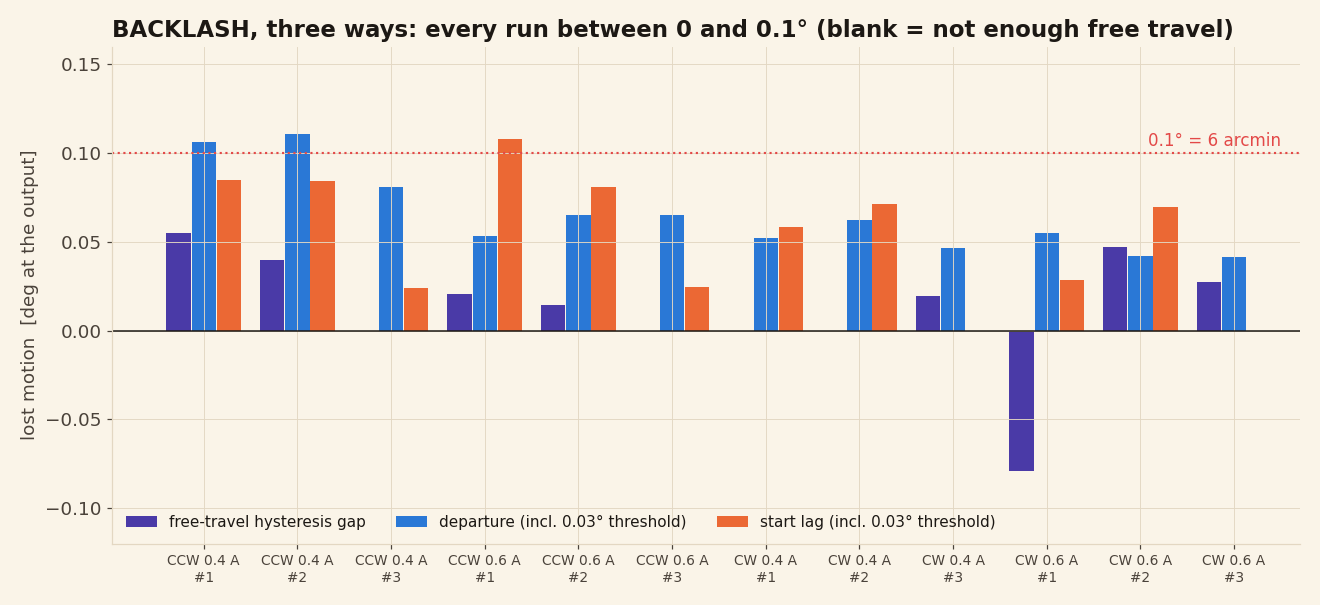
Our measurement floor is about 0.02°, so we call it about 2 arcmin typical, 6.7 arcmin worst case. What you'll actually feel at the output is the elastic twist above, not slack.
How it compares
To keep this fair, we plotted our drive at its worst reading against the listed maximums of off-the-shelf NEMA 17 gearboxes. Even at its worst it has less backlash than every planetary gearbox under $200, at a fraction of the price. Metal strain-wave gearboxes are tighter still, from about $100.
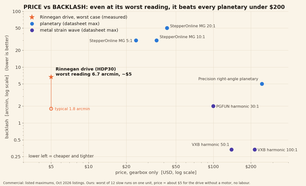
Commercial figures are listed maximums and gearbox-only prices from October 2026 listings, which move: StepperOnline MG series via Oz Robotics and eBay; precision right-angle planetary; PGFUN harmonic 30:1; VXB harmonic 50:1 and 100:1. Ours is the worst single reading of 12 slow runs on one unit (0.111°, with the detection threshold left in), and about $5 for the drive without a motor. The script is compare_cots.py.
The slow runs also give a cleaner stiffness, because there's no impact on the way in: 39.5 N·m/rad on the loading side, in line with the unloading numbers above. One unit, all within a few degrees of the same arm position. Backlash can vary around the output revolution, so a check at a few more positions is next.
<transmission-error/>
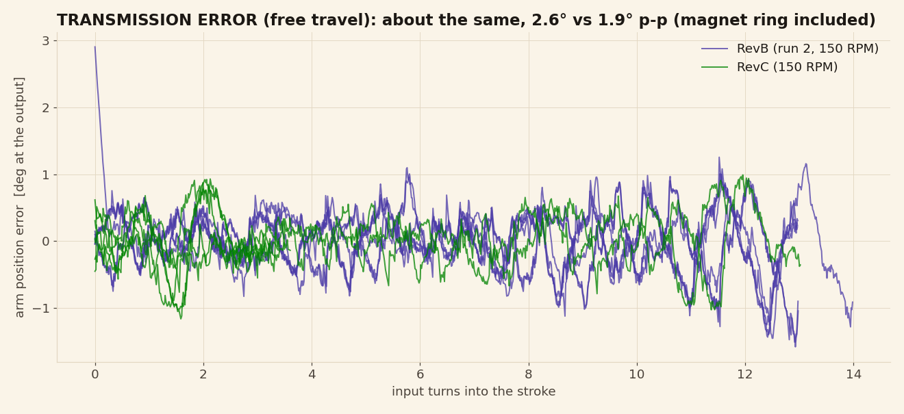
About the same as v1.0: 1.9-2.1° peak to peak against 2.3-2.7°, with the same rms. Most of it is the spacing of the magnets on the output encoder ring, not the gears, so this rig can't tell us whether the alignment helped here.
<endurance/>
Later the same day we built a second unit with a fresh PLA flexspline and ran it until it broke: a 21 s static hold, then 20 minutes of reversing strokes at 0.4 A, then shorter runs at 0.6, 0.8, 1.0 and 1.2 A. Every stroke drove the arm into a cell and held it there for 4 s.
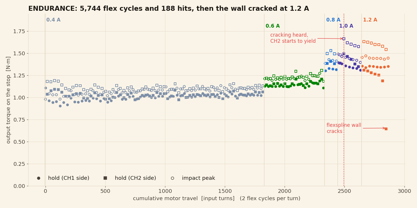
- 5,744 flex cycles and 188 hard stops at 1.0-1.2 N·m, with no damage. That's 2,872 motor turns, 96 output turns, no tooth skips, and the stop positions never drifted. The held torque even crept up about 8% over the first 20 minutes as it ran in.
- Damage started on one hit. 38 s into the 1.0 A run, an impact peaked at 1.67 N·m. That's when we heard it crack. The earlier unit started cracking at about 1.5 N·m.
- After that, it gave way a little more on every hit in that direction, and broke on the 12th.
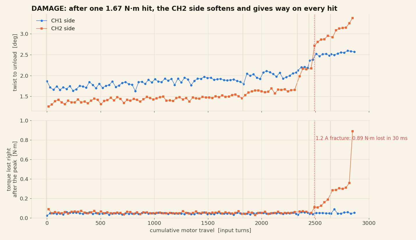
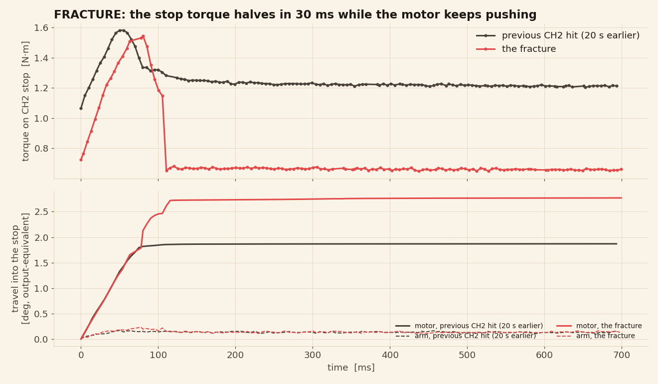
The other direction never yielded. Its impacts topped out at 1.49 N·m, and it still held 1.35 N·m on the very last hit, after the crack. So we read this as "the bigger impacts did the damage", not as one weak direction.
More current doesn't mean more torque
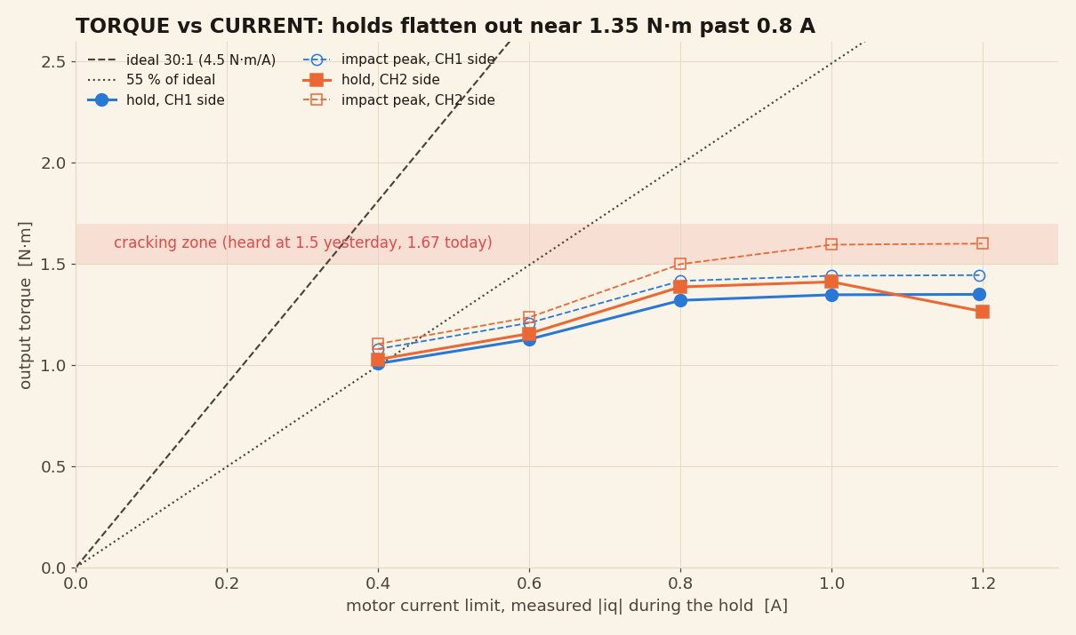
The motor on its own stays linear all the way to 1.2 A, so the ceiling is in the gearbox: static efficiency falls from 56% at 0.4 A to 25% at 1.2 A. What extra current does buy is harder impacts, and those are what cracked the wall. On a NEMA 17 like ours, about 0.6 A is the sweet spot.
It holds its position with the motor off
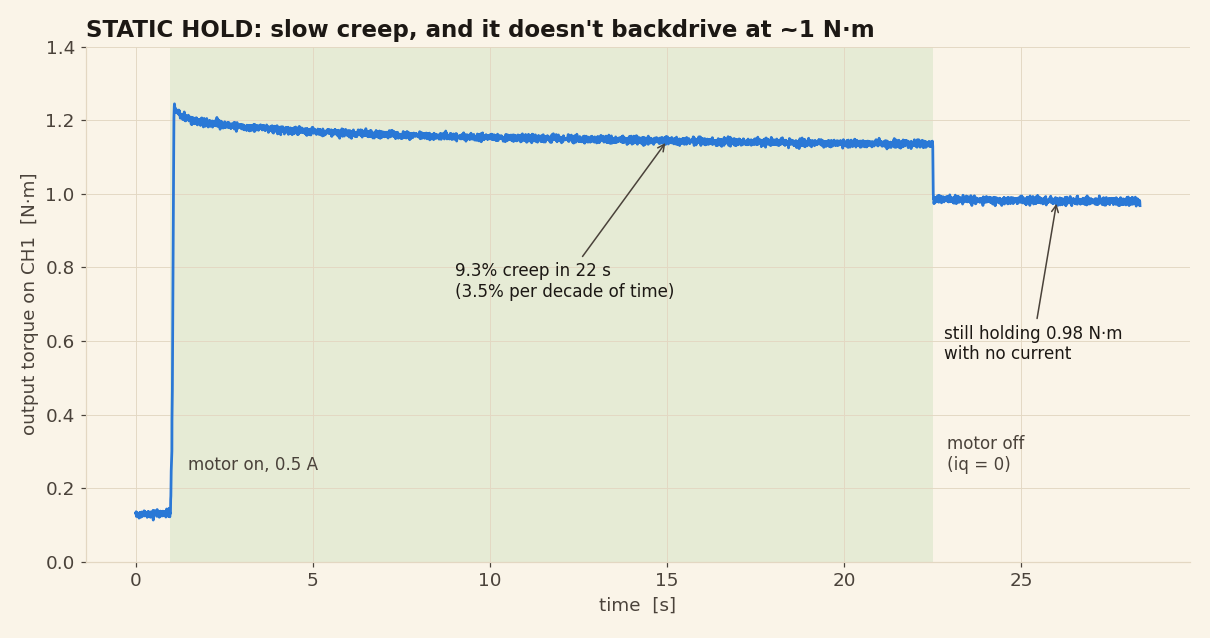
- It doesn't backdrive at about 1 N·m. With the current at zero, the output kept pushing 0.98 N·m into the cell. Friction in the mesh and the wave generator holds the load. That's handy for an arm joint. It also helps explain the torque ceiling above: at high current, much of the motor's effort squeezes the flexspline instead of turning the output.
- Creep: about 3.5% per decade of time. 1.24 down to 1.13 N·m in 21 s, with nothing moving. Every 10× longer you hold, expect roughly another 3-4% to relax.
- It softens a little as it warms. Over the 20-minute run it got warm to the touch and needed about 12% more twist for the same torque, on both sides, with no other sign of damage.
<what-this-means-for-you/>
- Keep peaks under about 1.3 N·m. It survived thousands of cycles at 1.0-1.2 N·m, and the wall started cracking at 1.5-1.67 N·m on both units. Impacts count.
- Limit motor current to about 0.6 A on a NEMA 17 like ours. Past 0.8 A the held torque stops rising, but the impacts don't. Your motor and driver will differ, so check against your own setup.
- Don't wait for a buzz. v1.0 warned you by ratcheting. v2.0 cracked without skipping, so the first sign of overload may be damage you can't undo.
- Life past a few thousand cycles is the open question. 5,744 cycles is about 40 minutes of running. A multi-hour test below the limit is next. If you run one for longer, tell us how it went.
- Avoid slamming hard stops at speed. Impacts gave the highest peaks we saw (1.59 N·m on a 1.49 N·m hold).
<method-and-caveats/>
- Three units. The comparison with v1.0 is one unit and three holds, the endurance runs are a second unit, and the slow backlash runs are a third. Printed parts vary: static efficiency at 0.4 A ranged from 41% to 56% across them.
- The first unit's cracking and breaking torques are approximate. They were heard after its recording, so they're not in its CSV. The second unit's crack and fracture are in the endurance data.
- Two changes at once. PLA and alignment changed together.
- Peaks include impact. The arm hit the cells at 150 RPM. Holds are medians over the steady part.
- Resolution. Logging was about 160 Hz on this run. Three rows of the output angle came through blank and are filled in by interpolation.
<raw-data/>
Same columns as the v1.0 data: time_s, ch1_n
and ch2_n (load cells in N), input_deg (motor
angle, wrapped), output_deg (MT6701 angle, wrapped, about
12 turns per output turn), current_cmd_a and
iq_a / id_a. The comparison script reuses the
v1.0 scripts and data, so put all the CSVs from both reports in one
folder, the scripts in a subfolder below it, and run
python revc_analysis.py,
python endurance_analysis.py or
python backlash_analysis.py. For the backlash script,
unzip the slow runs next to the CSVs so they sit in a
gearbox2-backlash folder.
Looking for the older numbers? The v1.0 test and the HD20 torque test are in the archive.